Research
Friction Stir Welding and Processing
Friction stir welding (FSW) is a solid-state joining process consisting of a [nominally] non-consumable rotating tool that plunges into two workpieces and traverses along the joint line, mechanically intermixing the two workpiece materials. The frictional heating and plastic deformation generate enough heat to elevate the weld zone temperatures well into the hot-working regime where metal alloys are easier to deform. However, the process does not cause bulk melting. Compared to melting-based (fusion) welding processes (e.g., arc welding), the lower temperatures in this solid-state process cause less residual stress (i.e., distortion) and embodied energy in the weldment. The severe plastic deformation (shearing) that happens in the weld nugget results in grain-refinement that often results in distinct mechanical and corrosion advantages over traditional fusion-based joining methods.
Dr. Pfefferkorn’s lab has been studying the friction stir welding (FSW) and processing (FSP) of aluminum alloys since 2003. Some of the research topics include laser-assisted FSW; energy consumption of FSW; Unit Process Life Cycle Inventory (UPLCI) for FSW; closed-loop control of tool-work interface temperature during FSW; nanoparticle emissions during FSW; FSW of dissimilar alloys; causation of voids / cavities remaining in friction stir welds; numerical simulation of cavity formation during FSW; and direct observation of metal flow during FSW. In June 2022, Dr. Pfefferkorn, his students, and scientists at the Advanced Photon Source (Argonne National Laboratory) conducted experiments that directly observed metal flow inside a workpiece during FSW in order to study the cavity opening and filling advancement to the friction stir tool during each rotation of the tool. This opening and closing of cavities happens during all observed welding conditions, no matter if the process parameters produce a fully-consolidated (fully dens, with no porosity) joint or one that has cavities / voids remaining in it.
Friction Surfacing
Friction surfacing, is an emerging solid-state additive manufacturing technology that produces fine-grained coatings with excellent surface and corrosion properties. Friction surfacing was invented in 1941 for the purpose of creating hard coatings. However, a growing interest in the technology has materialized recently for depositing multiple layers on top of another, i.e., additive manufacturing. A rotating solid rod is pressed against the substrate under an applied axial load and is traversed along a defined tool path. Frictional heating at the local contact zone between the consumable rod and the substrate due to the elastoplastic deformation of the rod, generates a viscoplastic rubbing interface at the rod tip. The material exiting the rubbing interface splits, with some curling away from the substrate (flash) and the rest being deposited onto the substrate. Material is continuously deposited onto the substrate surface by traversing the tool while it rotates and plunges. Compared to other solid-state metal additive manufacturing processes (e.g., additive friction stir deposition), friction surfacing can be performed on any CNC machine tool. In other words, most manufacturers do not have to buy new equipment, and certainly not specialized equipment, to be able to perform friction surfacing. The process is particularly well suited for repair and remanufacturing operations as well as the solid-state deposition of high-temperature high-strength alloys.
Dr. Pfefferkorn’s lab has been studying friction surfacing since 2018. Research topics have included: using friction surfacing to seal stress corrosion cracks in stainless steel canisters; multi-layer deposition of stainless steels and aluminum alloys; direct reuse of metal cutting chips through friction surfacing; consolidating loose feedstock (metal chips, metal powder) with friction surfacing; energy consumption of friction surfacing; understand how a bond forms during friction surfacing and the sensitivity of the bond properties to process parameters.
Multi-material Additive Manufacturing
Under Construction
Laser Polishing and Structuring
Laser polishing and structuring melts a shallow layer on the surface of a metal alloy to allow surface tension, and potentially other forces, to redistribute material. To reduce/eliminate surface asperities, i.e., get a smoother surface, constant process parameters are employed in order to maintain a consistent melt pool size. When the goal is to create surface features (structures) then the energy input per pulse or per unit time is varied in order to cause changes in the melt pool size, which end up redistributing material laterally across the surface. Continuous wave polishing is generally used for smoothing out rougher surfaces, whereas pulsed laser polishing is well suited for smoother initial surface topographies.
Laser polishing is a non-contact, volume neutral surface smoothing process suitable for metallic parts, where conventional polishing methods are unproductive and/or uneconomic. By using melting instead of material removal there is very little chance that this finishing process will bring a part out of dimensional tolerance. Laser polishing is automated, repeatable, and integrates particularly well into other laser-based manufacturing operations: e.g., welding, cutting, additive manufacturing.
Dr. Pfefferkorn’s lab has been studying laser polishing since 2005. Research topics have included: pulsed laser polishing; continuous-wave polishing; pulsed laser structuring; effect of melt pool size and melt duration on flow and smoothing; modeling of laser polishing and structuring; direct observation of laser remelting by using high-speed high-energy x-ray imaging; chemical homogenization of metal surfaces by remelting; polishing laser powder bed fusion components.
Measuring Tensile Strength of Single-layer Deposits
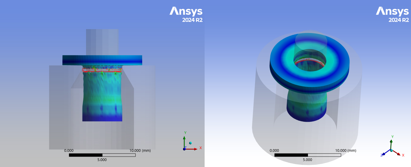
With the development of a novel material or manufacturing process, characterization of the resulting material/product is arguably the next step in transitioning from research limited application to commercial applications and products. In the case of friction surfacing of similar or dissimilar metals, there is not a standardized test that quantifies the bond strength of the metal cladding to the substrate metal. Metal deposition from the friction surfacing produces a single layer cladding that is typically less than 2 mm thick. The standard metal “strength” testing is ASTM E8/E8M, tension testing of metallic materials. For a typical tensile test, the test sample gage sizes (length of the test region of the sample) range from 200 mm to 25 mm. With a cladding of less than 2 mm it is difficult and costly to produce a test sample that would meet the ASTM E8M guidelines with a gauge length less than 2 mm and containing the boundary layer of the cladding and substrate. Using a US Department of Defense Military specification, MIL-J-24445A, that certifies the minimum required solid-state bond strength of explosive welded aluminum to steel plate, we are attempting to modify the Ram tensile test for friction surfaced products. This work involves developing a specific design and manufacturing tolerances for an appropriately sized test sample, the manufacturing process to make the samples, and validation of test results to that of ASTM E8M.
Instrumented Cutting Tools
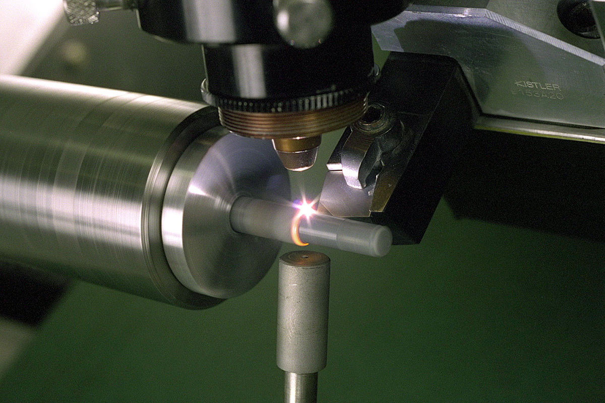
The objective of this line of research is to embed thin-film sensors in the hard coating system that is applied to metal cutting tools in order to observe what is happening in the very small region under the metal cutting chip. Only be being located as close to the tool-chip contact area can one observe arguably the most important region of a metal cutting process. These observations can be used to conduct fundamental research, create a digital twin of the tool or workpiece, and implement novel closed-loop process control strategies for high-value add metal cutting operations. For example, push the cutting speed, hence material removal rate, for titanium without exceeding the temperature at which the metal ignites, thereby lowering part costs. Dr. Pfefferkorn’s lab has been studying how to fabricate thin-film thermocouples directly on the rake face of a commercially available tungsten carbide cutting insert for accurately measuring the tool-chip interface temperature during metal cutting.
Thermocouples were sputtered onto the cutting insert using micro machined stencils, electrically isolated with layers of Al2O3, and received a top coating of AlTiN for durability. The result was a non-sacrificial thermocouple junction that was approximately 1.3 µm below the rake face of the tool and 30 µm from the cutting edge. It was determined that this particular configuration could capture tool-chip interface temperature transients at frequencies of up to 1 MHz, which enabled observation of serrated chip formation and adiabatic shear events. Measured temperature fluctuations during unstable cutting directly matched the transients in force data collected from a piezo-electric force dynamometer.
This method of measuring the tool-chip interface temperature shows promise for future research and smart manufacturing applications. However, further fundamental studies are required to understand the chemical, mechanical, and electrical effects of the materials used in this application and the very large stresses, temperatures, and gradients present in the cutting zone of the tool on electrical measurements.